Ensuring regular testing, maintenance, and field service can help mitigate the danger arc flash poses for people and property.
By Mose Ramieh III, CBS Field Services
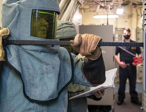
Whenever the topic of arc flash comes up, most of the conversation is around the dangers posed to nearby workers. And the costs of arc-flash injuries to technicians and their families cannot be overstated. For that reason, we see industrial consumers of electricity focus their arc-flash safety efforts on arc flash studies, necessary labeling, personal protective equipment (PPE), and remote racking/switching solutions to protect people in the event of a fault.
But arc flash poses problems for more than people. An arc flash can result in tens and even hundreds of thousands of dollars in equipment repairs and lots of unplanned downtime and even more lost revenue. With this in mind, arc-flash knowledge can translate to big time bottom-line savings. Understanding the arc-flash calculations changes in the 2018 edition of IEEE standard 1584, as well as ensuring regular testing, maintenance, and field service, can help mitigate the danger to people and property.
This article looks at common field-service activities that can reduce the risk of an arc-flash event and mitigate the damage when the unexpected happens. It is part of a series of articles from Group CBS electrical companies that look at the causes of arc flash and how remote racking solutions, testing, maintenance, and other shop and field services can reduce arc flash danger to personnel and equipment.
The Dangers of Arc Flash
Arc flashes can be caused by, among other things, tools left inside equipment, electrical installation issues, manufacturer defects, or improper maintenance of electrical equipment. An arc flash incident can generate an electric arc with a temperature of 35,000°F and an arc blast that expels dangerous pressure waves. Both can have catastrophic consequences for nearby qualified electrical workers and equipment.
Accurate arc flash calculations help facility managers determine the risk and the level of PPE necessary to reduce injuries and equipment damage. Updates to the IEEE 1584 standard that should be taken into consideration for calculating incident energy and arc-flash boundaries include revisions to voltage classifications, bolted fault current levels, the electrode configuration factor, enclosure size, minimum distances, and the removal of the system grounding variable. An experienced field service technician can ensure the parameters OEMs set for equipment are in line with the IEEE 1584 updates for arc flash calculations. Your arc flash study should also take the maintenance state of equipment into account.
First Stop: Maintenance
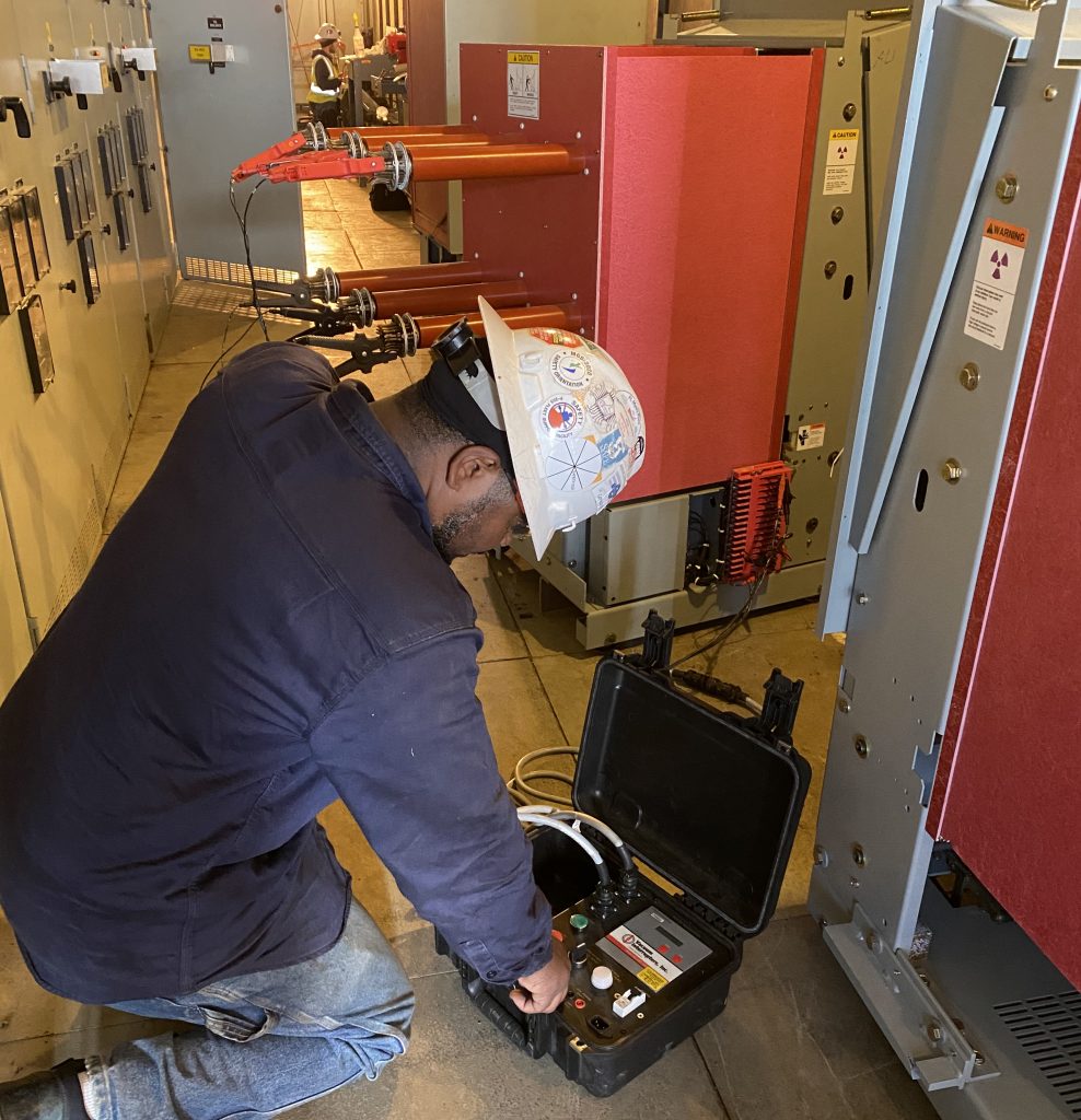 Proper maintenance is the first line of protection against arc flash. Circuit breakers help reduce the energy available for an arc flash by sensing fault conditions and interrupting the flow of power, so a circuit breaker’s mechanical system is of the utmost importance. If a circuit breaker isn’t performing as it should, the information on the arc flash hazard label will not be accurate.
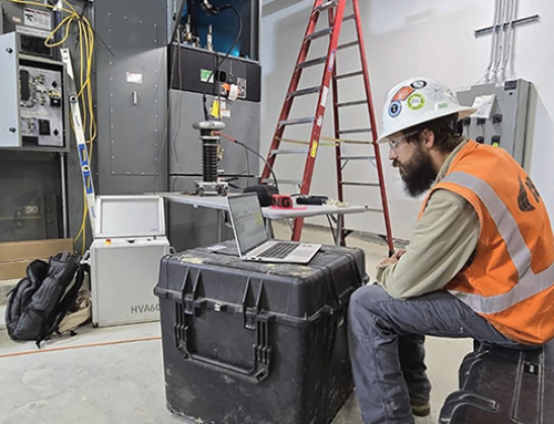
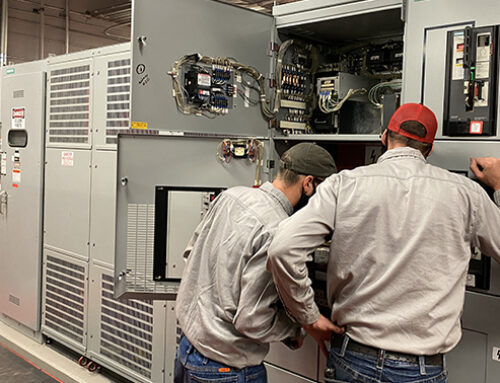
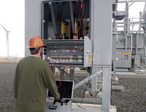
Maintenance service improves a breaker’s operation and reliability. Conducting visual inspections, mechanical verification checks, electrical testing, and repairing low-, medium-, and high-voltage electrical apparatus as part of a maintenance program for your facility is the best way to keep your electrical system functioning safely.
The ANSI/NETA MTS-2019 Standard for Maintenance Testing Specifications for Electrical Power Equipment & Systems incorporates comprehensive field tests and inspections to assess whether electrical power distribution equipment and systems are reliable, suitable for continued service, or in need of maintenance. Circuit breaker timing tests are another way to determine if equipment is operating within OEM parameters, and a technician can evaluate if those parameters are up to the latest standards.
Industrial Trends Increase Arc-Flash Risk
While maintenance and testing are the first line of defense, facility managers should also ensure electrical equipment and systems are ready for decades of safe and reliable service. The available fault current energy that powers arc-flash events is only increasing. Facilities are commonly increasing the sizing (ampacity) of their power system equipment. Low-voltage switchboards of 4,000 to 5,000 amps are becoming increasingly more commonplace. This power is necessary for processes and manufacturing and to save cost over installing multiple smaller systems.
Outside the facility, at the service entrance to industrial plants, utility companies are working to reduce the danger of increasing energy stores by installing arc-resistant switchgear. If you aren’t familiar with arc-resistant switchgear, picture military-tank-like switchgear with plenums (ducts) to route the force of a blast out of the room, thereby mitigating the likelihood of a switchgear explosion injuring a qualified worker. These solutions help but can’t completely remove the danger at the plant entrance, and they do nothing to protect the electrical distribution network inside.
Inside the facility, circuit breakers are connected to one another as part of a coordinated network of protective devices to obtain a balance between power system reliability and equipment safety (not qualified worker safety). In some cases, turning on motors will result in temporary overcurrent conditions that can lead to nuisance faults from circuit breakers and other protective gear. In these cases, the power distribution system is designed to allow overcurrent faults to occur and persist for second(s) while the downstream breakers closest to the fault time out and trip, allowing the plant to continue operations while limiting the equipment that goes offline. Again, you can see how this design seeks to find a compromise between industrial operations and the safety of equipment and personnel.
Fortunately, technology is evolving to provide improved safety for qualified electrical workers and system reliability, creating a win-win for the facility and the qualified worker. Some of these solutions include:
- Arc-flash relaying
- High-speed bus differential relaying
- Maintenance bypass switching
- Arc-quenching switchgear designs (not addressed in this article)
- Gas-insulated switchgear (GIS)
- High-resistance grounding (HRG)
Arc-Flash Relaying
Time is one of the three parameters that define the severity of the arc flash, along with distance and energy. Many of the solutions discussed here are about shortening the time the arc-flash fault lasts to reduce available energy and subsequent damage.
Arc-flash relay technologies work to trip faster than traditional overcurrent protection by using a combination of inputs. The typical inputs are fault current and light sensors and/or pressure sensors (Figure 1). The sensors consist of fiberoptic point sensors or a clear-jacketed fiber loop. Point sensors are typically installed in switchgear compartments (breaker enclosures). Fiber loops can be routed through several sections, such as bus compartments.
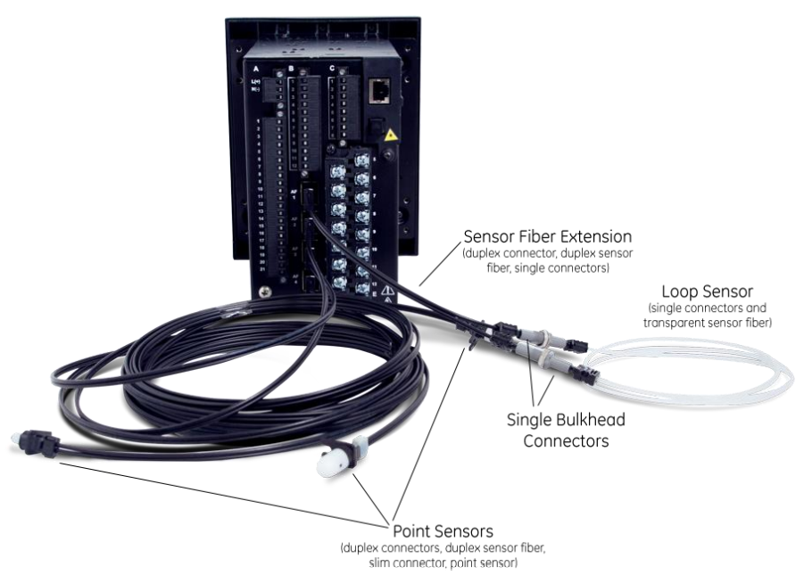
Figure 1 Arc-flash relay technologies work to trip faster than traditional overcurrent protection by using a combination of inputs, such as light sensors and/or pressure sensors.
These devices add a level of complexity to standard testing. Two tests are required to verify proper operation:
- A traditional overcurrent test would prove that the relay operates per its coordinated settings (time delay).
- The second test would be a combination of both the overcurrent and a light input.
High-Speed Bus Differentials
The waveform in Figure 2 is a fault that was captured by a power system relay. Note the fault that occurs on A phase. Long story made short: A technician who was in the wrong cubicle unintentionally grounded an energized 13.8 kV system conductor. Technician note: Always perform a live-dead-live check of your voltage detection meter. To everyone’s amazement (and good fortune), the only thing that happened was that the facility was plunged into darkness. No explosion, no arc flash, not even a scratch on the grounds. This fault, which was cleared by a high-speed bus differential, demonstrates the value of clearing faults quickly (three cycles in this case).
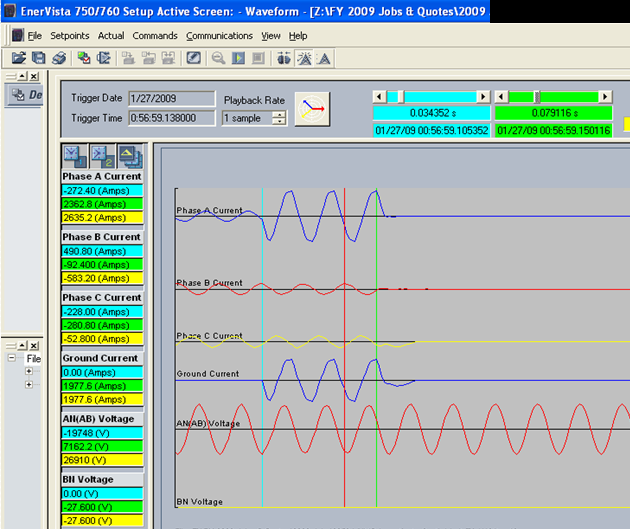
Figure 2 This waveform is a fault that was captured by a power system relay.
Maintenance Bypass Switches
Clearing faults quickly and at lower current values is the theory of operation behind maintenance bypass switches. As an example, to maintain system reliability, an instantaneous trip on a low-voltage main circuit breaker may be set to 32,000 amps (8 times the rating of a 4,000-amp breaker). This setting is great for reliability, but not for safety.
While racking a breaker in or out in a maintenance situation, the switch is used to turn on an alternate group of settings. In this alternate group of settings, the instantaneous value is changed to a lower setting. This means that instead of 32,000 amps, the breaker could trip instantaneously as low as 6,000 amps (depending on trip unit type). This reduces the amount of fault current necessary to activate the instantaneous element and eliminates the time delay to clear a fault, should one occur.
Testing these systems is straightforward. Test the breaker at its normal settings. Place the switch in maintenance mode. Verify the settings group changes. Verify that the breaker operates at the lower current setting. An important final note for power system reliability: Always remember to return the maintenance bypass switch to its normal position (Figure 3).
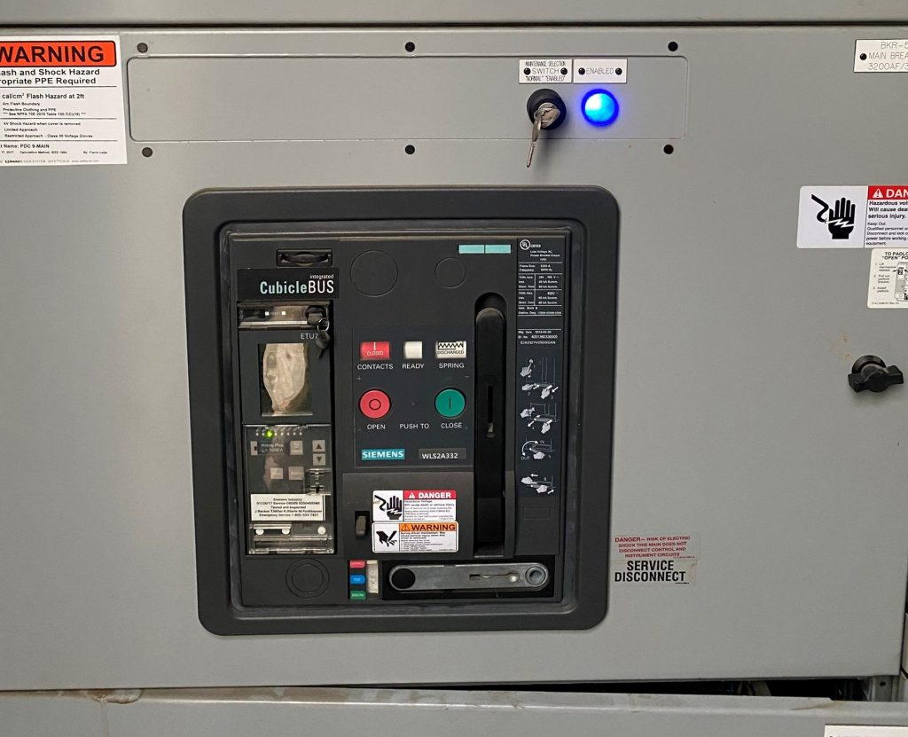
Figure 3 Always remember to return the maintenance bypass switch to its normal position.
Gas-Insulated Switchgear (GIS) and High-Resistance Grounding (HRG)
Two brief thoughts on GIS and HRG to eliminate arc-flash hazards:
- GIS gear in a nutshell: It has no exposed energized parts and therefore no arc-flash hazards.
- HRG: Most (but by no means all) arc-flash events begin as a phase-to-ground fault. By installing a resistor in the ground circuit, HRG systems eliminate arc flash in these situations by limiting the fault current to as little as 5 amps. Systems provide alarming of a ground fault, and manyinclude methods and components that allow for identification of the faulted circuit.
Conclusion
It may be difficult to alter your system by installing arc-flash relaying or HRG systems. These take money and outage time to reduce the hazards of arc flash and still may not reduce the hazard to an acceptable level. In contrast to other systems, the use of remote racking and switching is easier to implement. By modifying how these common system tasks are accomplished, qualified workers can remove themselves from the arc-flash boundary and still perform their jobs.
No matter the equipment you employ, maintenance testing of the power system is a critical factor in ensuing the continued safe and reliable operation of your electrical equipment throughout its life span.
For more information on how qualified field-service companies can help you conduct new arc-flash calculations or mitigate your arc-flash dangers, feel free to contact us.
Mose Ramieh III is vice president, business development at CBS Field Services. A former Navy man and a Texas Longhorn fan, a vlogger, a CrossFit enthusiast, and a slow-cigar-smoking champion, Mose has been in the electrical testing industry for 24 years. He is a Level IV NETA Technician with an eye for simplicity and utilizing the KISS principle in the execution of acceptance and maintenance testing.
Read the whole series:


